1 I56-2248-00
XR2B Detector Installation/Removal
Tool for use with System Sensor
Low Prole Intelligent Detectors
OPERATING INSTRUCTIONS
3825 Ohio Avenue, St. Charles, Illinois 60174
1-800-SENSOR2, FAX: 630-377-6495
www.systemsensor.com
General Description
The XR2B Detector Installation/Removal Tool is designed
for use with System Sensor low prole intelligent detectors.
This includes photoelectric, photoelectric with heat, ion-
ization, and heat detectors. This installation/removal tool
does not work with the laser detector. This tool permits
installation and removal of detectors in elevated mounting
locations up to 15 feet (4.6 meters) high when it is used
with XP-4 extension poles (ordered separately).
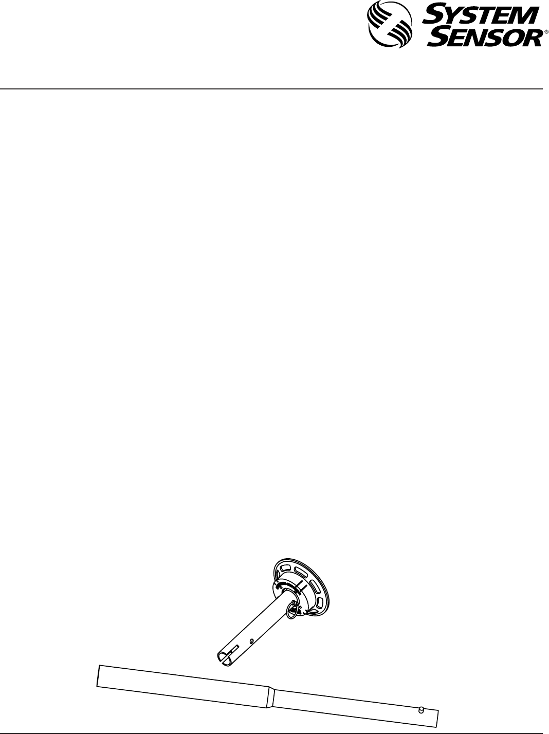
Tool Assembly And Disassembly
The XR2B installation/removal tool consists of a head as-
sembly and connecting tube that is used with a set of XP-4
extension poles sold separately (see Figure 1).
To assemble the tool, attach the head assembly to one of
the XP-4 extension poles by sliding the small end of the top
extension pole into the coupler end of the head assembly.
A hole near the end of the tube on the head assembly ts
over the button of the extension pole to lock the head as-
sembly to the extension pole. The extension poles lock to
each other in the same way.
To disassemble, depress the lock button until the head as-
sembly can be disengaged from the extension poles. The
extension poles can be separated from each other in the
same manner.
Detector Installation
To install a System Sensor low prole intelligent detector
into a low prole base:
1. Insert and rotate the detector head into the installation
Figure 1. XR2B Detector Installation/Removal Tool and XP-4 Extension Pole:
C0185-00
and removal tool until the detector head bottoms and
snaps into place.
2. Raise the tool to the ceiling until the detector head enters
the mounting base and the locking ears on the detector
head meet the ring inside the mounting base.
3. Rotate the tool clockwise until the locking ears enter
their respective slots.
4. Continue rotating the tool until the detector is fully en-
gaged in the base. When this happens the detector can-
not be rotated any further.
5. Carefully pull the tool from the detector head.
Detector Removal
To remove a System Sensor low prole intelligent detector
head from a base:
1. Raise the installation/removal tool to ceiling height, lo-
cate the tool over the detector, and push up and rotate
until the tool snaps onto the detector head.
2. Rotate the tool counterclockwise until the detector dis-
engages from the mounting base.
3. Lower the tool slowly and make certain that the detector
head is disengaged completely.
4. Continue lowering the tool. When the detector head is at
oor level, the detector can be removed from the tool for
inspection, testing, or cleaning.
Notes:
Plug-in bases have a built-in tamper-resist feature that, if
activated, must be disabled before the removal tool can be
used. See the instruction sheet packed with the detector
head for instructions on disabling the tamper-resist feature.
 (4 pages)
 Manymanuals.com
 Manymanuals.de
 Manymanuals.fr
 Manymanuals.it
 Manymanuals.pl
 Manymanuals.cz
 Manymanuals.es
 Manymanuals-pt.com
Commentaires sur ces manuels