BEAMHK
Heating Kit for use with the Transmitter/
Receiver Unit of Reflected Beam Smoke Detectors
INSTALLATION AND MAINTENANCE INSTRUCTIONS
3825 Ohio Avenue, St. Charles, Illinois 60174
1-800-SENSOR2, FAX: 630-377-6495
www.systemsensor.com
GENERAL DESCRIPTION
The BEAMHK allows the transmitter/receiver of the reflected beam smoke
detectors to operate in environments prone to the formation of condensation.2
Condensation forming on the beam detector unit may result in trouble or
false alarm conditions. BEAMHK will lessen the likelihood of condensation by
maintaining the unit at a temperature that is slightly higher than the surround-
ing air. The kit requires the use of an additional power supply for intelligent
units that do not have the automatic test feature. Heaters used in conventional
units, or intelligent units with the automatic test feature, will operate from a
power supply already used to operate the beam unit.
The kit includes the following parts:
Qty. Description
1 Transmitter/Receiver Heater Assembly
MOUNTING AND WIRING INSTRUCTIONS
1. Open front cover of the transmitter/receiver unit. Refer to the installation
manual provided with the beam smoke detector for instructions.
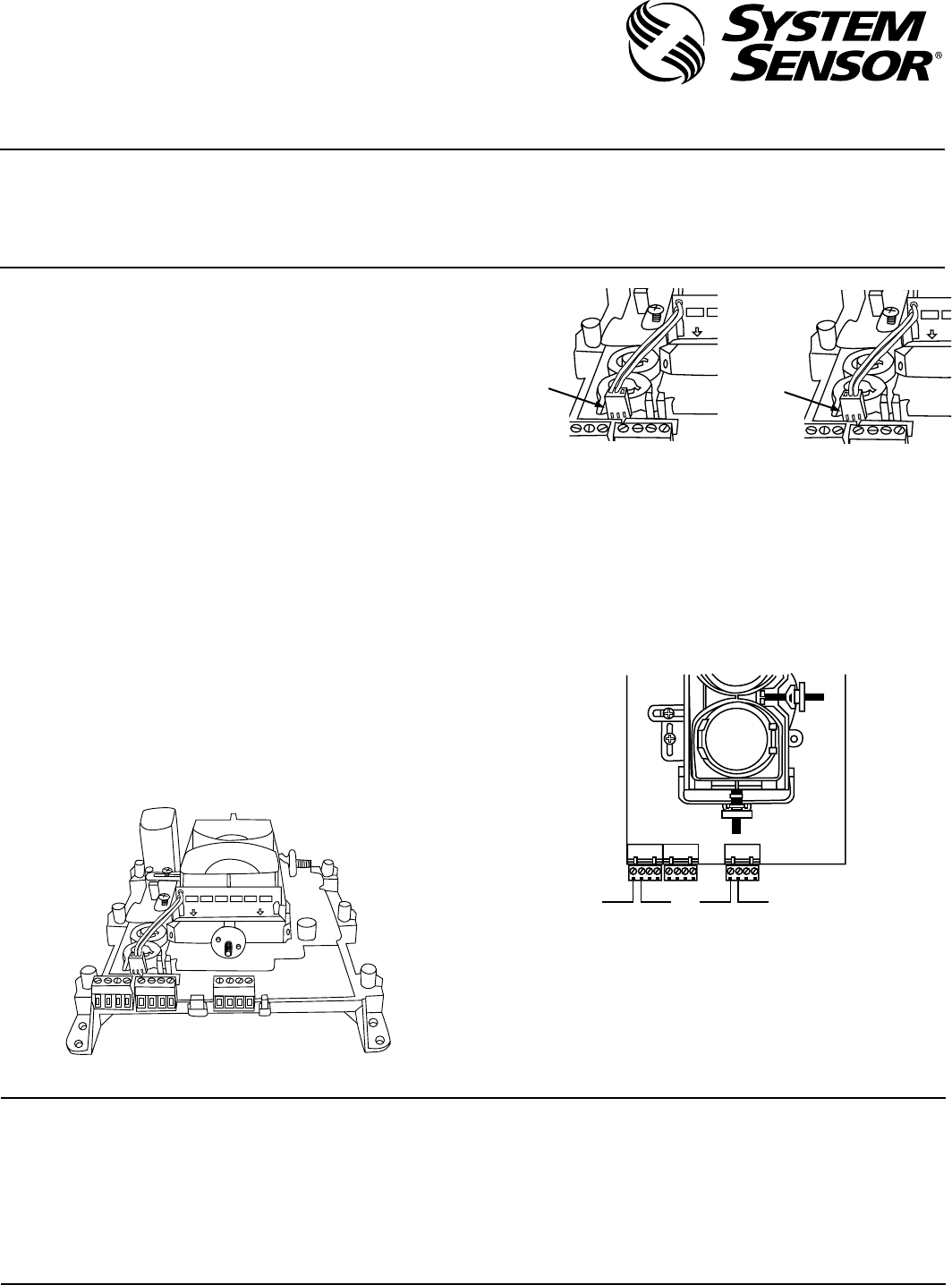
2. Plug the transmitter/receiver heater assembly PCB into the provided slot
on the optical assembly as shown in Figure 1. Insure that the connector
is on the left side, and the resistors are facing outward as shown.
3. Plug the connector into pin-header labeled HEATER on the transmit-
ter/receiver PCB as shown in Figure 2. Pin orientation does not matter.
Please insure that the connector is installed properly on all three pins,
or the heater will not work.
4. Connect the heater power supply wires as described below. If adding
the heater kit to an existing installation, insure that the power supply
connected to the beam detector is adequately rated for the additional
power consumption of the heater.
ELECTRICAL SPECIFICATIONS
Voltage: 15 to 32 V
Current: 92mA max at 32 V1
Power Consumption:
Nominal: 1.6 W at 24 V
Maximum: 3 W at 32 V
INTELLIGENT UNITS
Power is provided through terminal block T3-1 and T3-2 as shown. For units
with the automatic test feature, this power is provided to both the automatic
test feature and the heater. See illustration below.
CONVENTIONAL UNITS
Power is provided through terminal block T1-1 and T1-2 as shown in Figure
3. Power for the beam unit is also provided at these terminals. See illustration
below.
5. Align/realign beam smoke detector. Refer to the installation manual pro-
vided with the beam smoke detector for alignment instructions.
T3 T2 T1
(+)
Intelligent Conventional
(–) (–)(+)
FRONT
INSERT
INSERT
FIGURE 1:
FIGURE 3:
FIGURE 2:
INSERT
INSERT
OR
HEATER
HEATER
C0761-00
C0765-00
C0761-00
C0760-00
NOTES:
1. The electrical current specified is the requirement for the heater only.
The power supply must be capable of powering the heater, and other
devices that may be supplied through the same terminals.
2. The heater is intended for the prevention of condensation only. It is not
intended to increase or reduce the specified operating temperature range
of the beam smoke detector.
I56-2556-001
System Sensor warrants its enclosed heating kit to be free from defects in materials and
workmanship under normal use and service for a period of three years from date of
manufacture. System Sensor makes no other express warranty for this heating kit. No
agent, representative, dealer, or employee of the Company has the authority to increase
or alter the obligations or limitations of this Warranty. The Company’s obligation of this
Warranty shall be limited to the repair or replacement of any part of the heating kit which
is found to be defective in materials or workmanship under normal use and service
during the three year period commencing with the date of manufacture. After phoning
System Sensor’s toll free number 800-SENSOR2 (736-7672) for a Return Authorization
number, send defective units postage prepaid to: System Sensor, Repair Department, RA
#__________, 6581 Kitimat Road, #6, Mississauga, Ontario, L5N-3T5. Please include a
note describing the malfunction and suspected cause of failure. The Company shall not
be obligated to repair or replace units which are found to be defective because of damage,
unreasonable use, modifications, or alterations occurring after the date of manufacture.
In no case shall the Company be liable for any consequential or incidental damages for
breach of this or any other Warranty, expressed or implied whatsoever, even if the loss
or damage is caused by the Company’s negligence or fault. Some states do not allow the
exclusion or limitation of incidental or consequential damages, so the above limitation
or exclusion may not apply to you. This Warranty gives you specific legal rights, and you
may also have other rights which vary from state to state.
THREE-YEAR LIMITED WARRANTY
D400-87-00 1 I56-2556-001
©2010 System Sensor
 (13 pages)
 Manymanuals.com
 Manymanuals.de
 Manymanuals.fr
 Manymanuals.it
 Manymanuals.pl
 Manymanuals.cz
 Manymanuals.es
 Manymanuals-pt.com
Commentaires sur ces manuels